

Jordan Hofstrand and Ash Plasek
We’re big fans of Magic: The Gathering.
For the uninitiated, Magic is a deck building card game centered around playing cards that interact with each other in ever more complex and aggressive ways until you can out-grow, out-attack or out-wit your opponents.
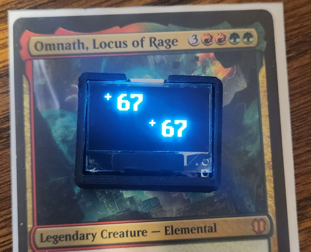
In Magic games, there is often a need to keep track of accumulated health points or effects put on a creature using counters, which are most often represented by using dice as a counting tool. This works pretty well, but we wondered what would happen if you mixed Magic with a dramatic overengineering of counters.
Initial Concept
We figured, if we crammed a Microcontroller, a display, a battery, and some buttons into a box small enough to fit easily on a Magic card without interfering with the rules text, that might make for an improvement on the traditional dice counting method.
We set ourselves a few requirements for the counter:
- Extremely Compact: Small enough to fit inside the borders of the Card Art on a standard Magic card.
- Long Battery Life: Magic games can often last hours. The battery has to keep up.
- Easy to Recharge: USB charging, or easily swappable batteries are a must.
- Low Cost: If this is going to be a practical replacement for dice it has to be extremely cost effective. <$5 BOM would be ideal.
This lead us to begin looking at what would be the hardest challenges in achieving those goals. The Microcontroller and display we chose would be critical in keeping cost and power consumption down.
The Search for a microcontroller
The choice of Microcontroller was fairly straightforward, but had some repercussions down the line. A quick search for the cheapest microcontrollers on Digikey lead us to the ATTiny line. Particularly the ATTiny402. The ATTiny is a pretty basic microcontroller, but has a very enticing combination of lower power and low cost. The only downsides we noted where the relatively low amount of RAM (256 Bytes) and the low number of GPIO pins (6).
Initial prototypes where built using the ATTiny402. Only having 6 GPIO pins ended up being a challenge. 2 pins were dedicated to I2C communications with the display. 2 more where set aside for powering the display and I2C Pullups, so that we could turn them off in software to conserve power when the counter was not in use. 1 had limited functionality as it was shared with the programming and debug port (UPDI). This meant we didn’t have enough GPIO for the buttons we would need. We experimented with using a resistor ladder and the integrated Analog-to-Digital converter in the ATTiny to measure the state of multiple buttons using a single GPIO pin on the Tiny.
With the first prototype, we managed to get the Microcontroller brought up and talking to the display. We began experimenting with the button resistor ladder, and while we managed to get it working at a basic level, we found it very finicky and felt it would be difficult to make it work reliably at scale. We liked everything else about the ATTiny’s performance in in our initial testing however, and so we decided to move up the product line to the ATTiny404. The ATTiny404 is largely compatible with the ATTiny402, with the addition of 6 more GPIO pins. This allowed us to connect the buttons directly to GPIO pins, improving relability.
In hindsight, if we were to start this project again from scratch, we’d probably have gone with an ARM based microcontroller. While we had more than enough compute power for this application, the extra RAM and program space afforded by a higher end microcontroller would have made this a lot easier and more capable. The new generation of MSPM0+ microcontrollers from Texas Instruments looks especially promising due to it’s low cost, maybe even ending up cheaper than the ATTiny.
The Search for a display
The display was our next big challenge. The display needed to be tiny, extremely low power, cheap, and being the face of the counter it needed to look good.
We spent quite a bit of time investigating various display technologies. LCD was promising because of it’s extremely lower power consumption, but price turned out to be a challenge as a display plus a driver capable of controlling it turned out to be more expensive than alternatives. Additionally, most non-backlit LCDs have a gray-ish green backing that subjectively doesn’t look very good.
E-Ink was an exciting possibility because it shares the lower power consumption of LCD while producing a better image. However, the cost was prohibitively high, with E-Ink displays easily being several times the cost of an LCD.
LED 7-Segment displays where considered, but would have drawn far too much power to be practical in this application.
Which leaves OLED. The mass produced SSD1306 0.96in 128×64 Graphic OLED displays available from the likes of Adafruit and various generic brands are extremely affordable, and while they consume a lot more power than an LCD or E-Ink display would they sit comfortably below an LED 7-segment display in that regard while also providing a graphic display. These OLED breakouts (and later the bare display module) where chosen as our display for having the best combination of cost and power consumption, as well as a convenient form factor for this application.
The BEST BUTTON CONFIGURATION
We looked at a lot of user input configurations.
A touchscreen would have been really cool and opened up a lot of possibilties, but likely would have been prohibitively expensive.
We looked at capacitive touch buttons placed on top of the screen using an ITO coated glass sheet, but this would have been similarly quite expensive and made construction considerably more complicated.
Multiple prototypes where built with tactile switches flanking the display.
The solution we eventually settled on, was to place a set of 4 tactile switches behind the display. Rather than rigidly mounting the display to the circuit board that carries it, the display was taped to the PCB with a piece of very thick 3M double sided foam tape. This left a gap between the display big enough to fit tactile switches, and allowed the display to move slightly when you press on the corners. This way, the display moving would press against the buttons and actuate them. Poor mans touch screen.
Power
We looked at many options for powering the counter.
A solar cell was briefly considered, which may have been possible with the E-Ink or LCD displays, but an OLED or LED display made this impossible.
Various types of batteries were looked at. Coin cells were promising if a very low power display was chosen. 1/2AA batteries fit nicely behind the profile of the display, but were unfortunately very thick. 3xAAA were considered, but ended up being much too large.
Eventually, due to the very high power demands of the OLED display, it was decided that whatever battery we used would need to be rechargeable. As such, Lithium Ion cells quickly became the preferred option. Prototypes where built with the PRT-13853 from SparkFun because it was the largest Li-Ion cell we could find that would fit within the footprint of the display. 110mAh should be enough to give us several hours of battery life, and a very long time in sleep.
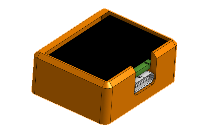
To go along with the battery, a Lithium Ion charge controller was added, and a USB-C port to receive power. We looked at a few different connectors and even built a prototype with a JST-PH 2 pin connector, but it was eventually decided that even despite the increased cost USB-C would add a lot of convenience.
Board Layout and mechanical design
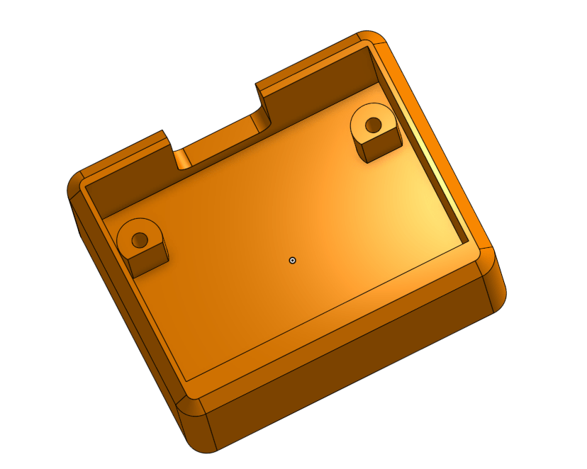
Cramming this all into such a small package was a fun challenge. The main constraint placed on the design was that we wanted the entire device to remain within the footprint of the display, and to be as thin as possible. As such, the PCB and battery had to fit in a very tight footprint and be stacked one on top of the other.
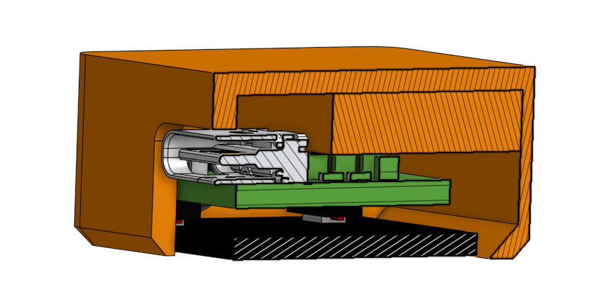
Assembly was also going to be a tricky process. The PCB would be assembled and then the display soldered to the board. After having soldered a few of these displays (and damaging some in the process), I am curious if using Z-Tape to attach the display to the board would have been a better idea. Perhaps a future experiment.
After soldering the display, the battery would be directly soldered to the PCB. Then the battery would be inserted into the housing and pushed all the way down, followed by the PCB. With the PCB resting on the mounting pegs, two M1.6 screws would be used to secure the board near the top. A single piece of 3M double sided foam tape would be attached to the top of the PCB, and the display would be pressed down onto it.
Software
All software for this project was written in C, using Microchip Studio.
Given the extremely limited RAM available on the ATTiny404, we had to get creative with the display. We did not have nearly enough memory onboard to hold and entire frame buffer. Instead we held a character map in memory. The display is large enough to fit 64 characters (4 lines of 16) at our chosen font size. Therefore we could fit an entire character map of the display in only 64 bytes. Each character in the font was then stored in program memory. When it came time to update the display, we would take the current pixel coordinate, convert that to a character map location, consult the character map for which character to draw and then lookup the pixel data in the font stored in program memory.
Later on logic was implemented that allowed for numeric characters to be drawn that were 4x the size of a standard character. This would be used to draw the counts on the main screen. This worked by consulting the font data in program memory, and using each pixel 4 times.
The software is capable of powering down the display and sleeping the CPU on command from the user, or automatically after around 30 minutes. When in power down state the device consumes very little power and can remain in this state for many days on a charge.
A basic menu was also implemented that allows the user to clear all counter values in memory or sleep the device.
Final Thoughts
While this seemed like a good idea at first, and while the final product is actually pretty cool to play with, it’s become pretty clear that the cost and complexity of such a device means it is of extremely questionable utility. We’ve got a whole list of things that could be done to improve the design further, but we think now is a good time to move on to a new project. The counter isn’t perfect, but it’s good enough and we learned a lot along with the way.
Potential improvements:
- Better Microcontroller
- Shrink PCB footprint enough that the battery could move up into the space occupied by components, thereby making the device a few mm thinner
- Improve button placement (They can get a little sticky at times)
- Improved processor power management
- Power microcontroller off VBat instead of regulated power to remove quiescent current when not powering the display.
- Add bluetooth for cool extra features?
- More software features, maybe a dice roll function and a single counter mode?
- The board layout could be redone to improve manufacturability. Various vias on the board are very small, making manufacturing costly and difficult.
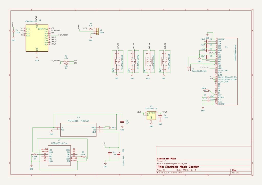
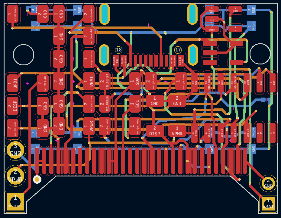
Schematic and PCB layout
Project Files
Full source code and PCB design files as well as a STEP file containing the main housing are available on Github.
https://github.com/Jordanayan/ElectronicMagicCounter
Useful sources
Adafruit Monochrome 0.96 128×64 OLED Graphic Display – STEMMA QT
https://www.adafruit.com/product/326
Was very helpful as a resource for designing the display portions of the board.
How much current does do OLED displays use?
https://bitbanksoftware.blogspot.com/2019/06/how-much-current-do-oled-displays-use.html
Was a very useful resource during early design work.
A tangent into display design
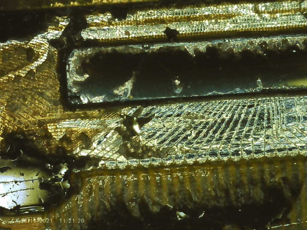
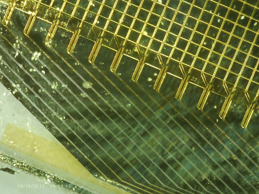
We were curious how these OLED displays are put together. So naturally we took one apart. The display appears to be made of two sheets of glass that are bonded together. Both panels are the same width, but the front is taller. On the back, the bottom glass covers most of the surface, but a small gap is present at the bottom which has been covered with some form of Epoxy. We removed the epoxy, and found that a silicon die has been bonded seemingly directly to the glass, and the traces connecting the die to the display also seem to be printed directly on the glass.

Leave a comment